👾 Extracting system files from a TL-WR841N v14 👾
Context
This article begins by exploring the analysis of the hardware and the serial console, before focusing on the reverse engineering of the firmware, which will be covered in a later article. The target product is a TP-Link N300 router. The router’s technical specifications will be presented in the following section.
This work is designed for anyone interested in the field of hardware analysis and hardware hacking. The complete research process, from information gathering to firmware extraction, including an alternative method of extracting system files via the UART, will be described in detail.
The main aim of this first article is to extract the system files from the UART of the TP-Link N300 router. The second part will be devoted to extracting firmware from flash memory and its reverse engineering.
Methodology
Below, the methodology followed:
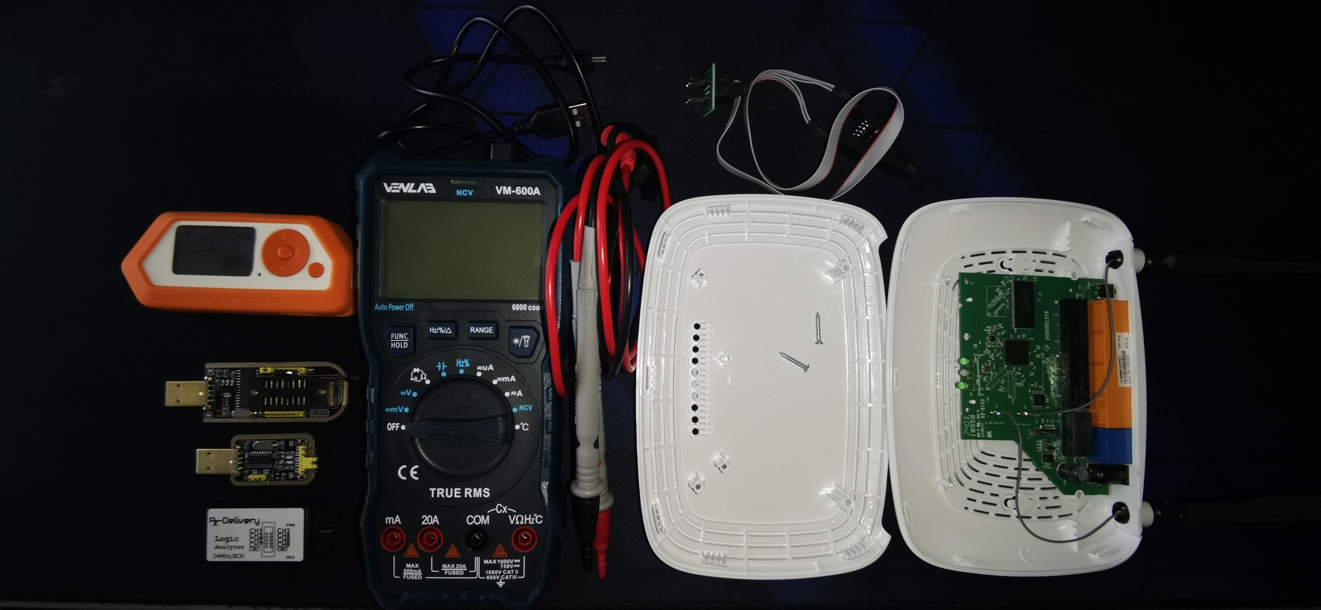
- Information Gathering: This part consists in gathering information about the product and its master components, in particular the chips.
- Interacting with the Serial Console: This stage involves interacting with the serial console via a serial communication protocol called UART, enabling access to the microcontroller system (MCU).
Information gathering
Information directly legible on the product
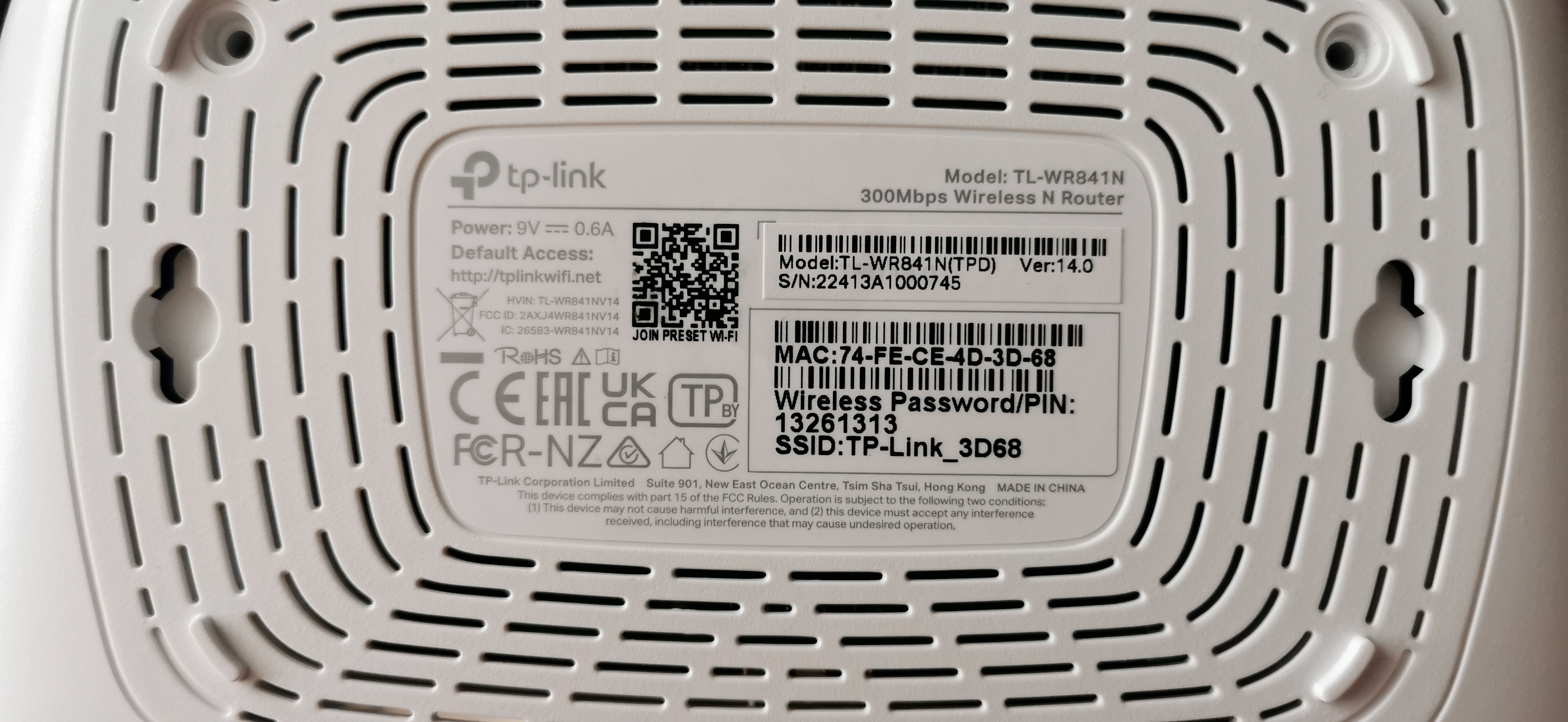
On the back of the product, you can find various interesting information such as:.
- The Model: TL-WR841N
- The Version: 14.0
- The Serial Number: 22413A1000745
- The power required to supply the product:
- 9V
- Direct Current (DC)
- 0.6A
As well as alternative information in relation to the target:.
- MAC: 74-FE-CE-4D-3D-68
- Default network password: 13261313
- SSID : TP-Link_3D68
Information on MCU chips
First of all, there’s a really useful site for gathering information HERE. It often gathers a lot of very useful information, on hardware, supported versions, firmware, serial console, … .
To verify the information collected on the chips from the above-mentioned site, retrieve the acronym/name of the manufacturer and the part numbers for each chip:.
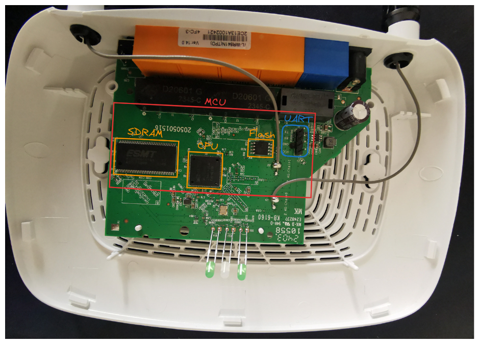
- SDRAM: ESMT M13S2561616A-5T
- CPU: MEDIATEK M17628NN
- Flash: cFeon QH32B-104HIP
A simple browser search will bring up the datasheets for the various chips. We also realize that the only good reference to be collected via this site is that of the CPU, which shows the importance of manually checking the information in order to validate it.
Finally, finding the serial console is often one of the first things to do. In the case of this product and this version, this is relatively straightforward, as the pins of the test points (TP) are referenced. I’ll explain in the UART section how to find the meaning of each pin manually. We’ll also see that there’s a little specificity that isn’t mentioned on the site.
- SDRAM: ESMT M13S2561616A-5T
- CPU: MEDIATEK M17628NN
- Architecture: MIPS
- CPU bit: 32-bit
- Flash: cFeon QH32B-104HIP
- Bootloader: uboot
In our case, the MicroController Unit (MCU) is made up of a CPU, a SDRAM for temporary memory (volatile memory) and a flash memory for permanent memory (non-volatile), as well as its serial console for interacting with the MCU using a serial communication protocol called UART.
UART
What is it?
Universal Asynchronous Receiver/Transmitter (UART) is an integrated circuit that enables asynchronous serial communication between two devices. It converts parallel data into a serial bit sequence for sending, and vice versa for receiving. The UART is essential for communication between computers and serial peripherals.
How do I find it?
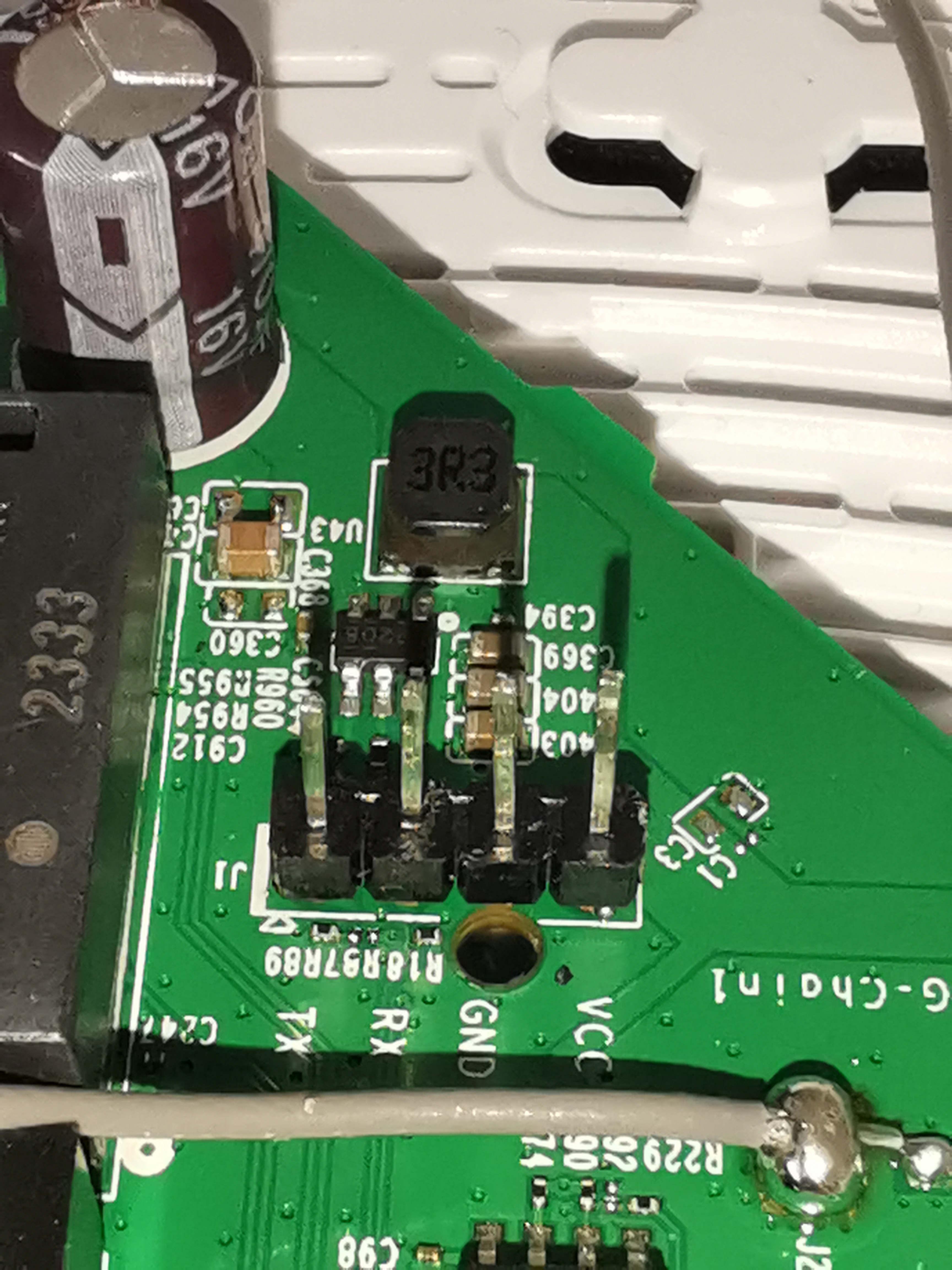
As mentioned above, in the case of this product, there is only a series of 4 test points and they are referenced. However, on a larger PCB, it’s more complicated to find them, so you can base your search on several pieces of information.
Look for 4 successive test points, find a ground on the equipment, place your negative probe (black) on the ground you have found as a reference point, then using the red probe test the voltage (V) of these 4 pins, normally you should find these values within the scope of our target:.
- VCC ≅ 3.3V
- GND = 0.0V
- RX = 0.0V
- TX ≅ 3.2V
Since VCC supplies 3.3V and GND is earth, the values are easy to interpret, but why do RX and TX have these values?
Since RX is the pin that receives, and has no interrupts, it’s natural to set its value to 0. For TX, it’s the pin that transmits, so its voltage is stimulated it’s a microcontroller configuration.
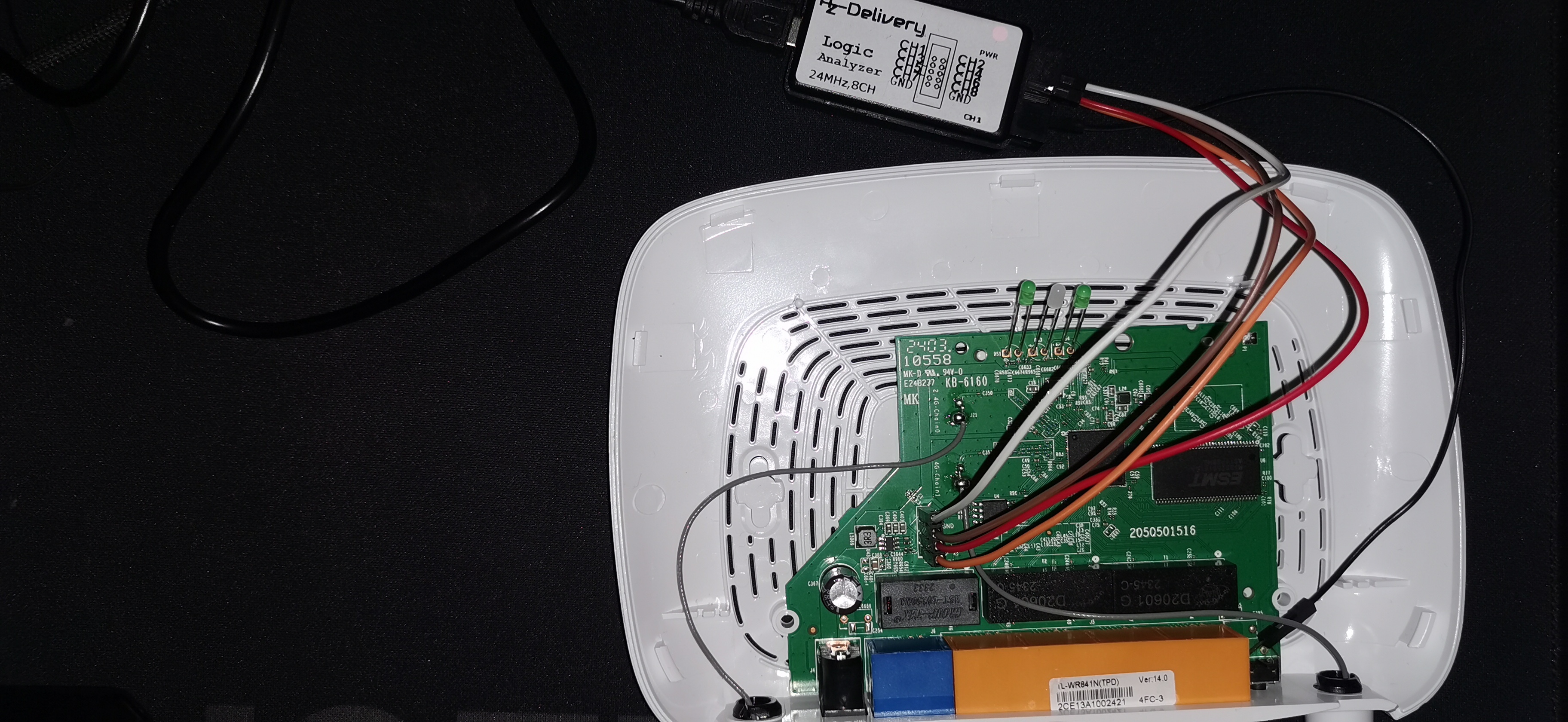
To validate the multimeter values (this process can be done in reverse), simply solder 4 pin headers.
Then connect the logic analyzer box (note that I connected GND of the box to a ground as for the multimeter).
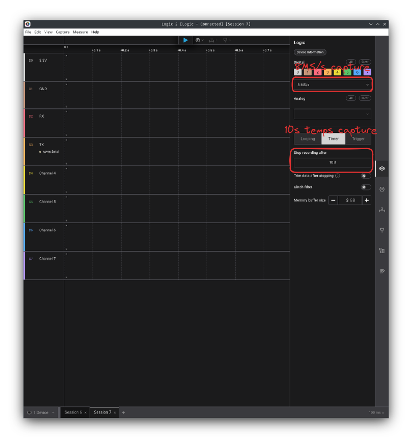
Then open Saleae’s logic2
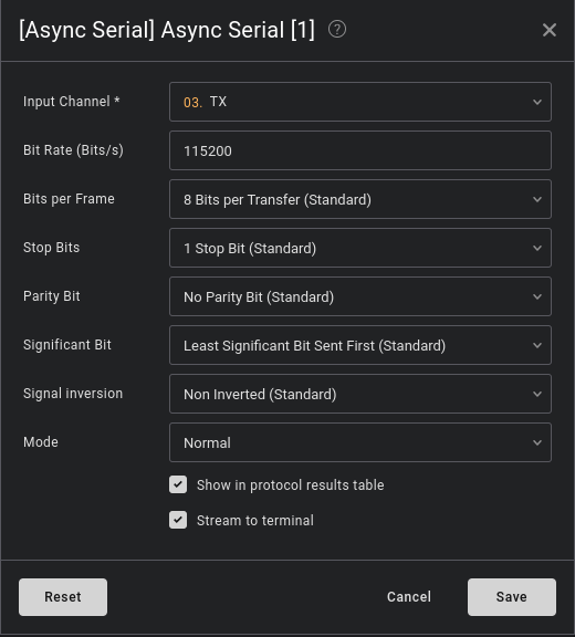
 The result obtained on TX shows that there is indeed data in transit. To decode it, all we need to do is find the right baud rate. To determine this, simply take the width of a positive bit and divide by 1 (e.g.: bd = 1 ÷ 8333µs). The result will give you an approximate value, and you can refer to the following list to find the exact value. In our case, it’s 115200 (as is often the case).
- 1200
- 2400
- 4800
- 9600
- 19200
- 38400
- 57600
- 115200
- 230400
- 460800
- 921600
Right-click and display values in ascii

We do receive data from TX, which is what we expected, even though we’re normally supposed to receive data starting with the bootloader, in our case u-boot and its version. Now let’s see how to interact with the serial console.
Interacting with the serial console
Use any USB to UART, I will personally use a CH340G.
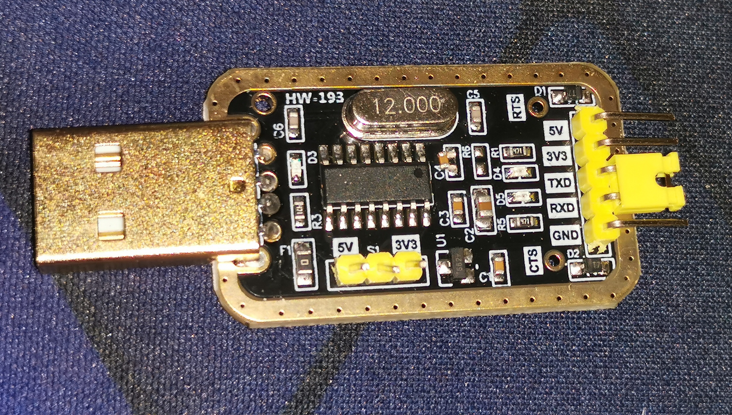
Make the connection according to the following diagram:
- TX => RX
- RX => TX
- GND => GND
- 3.3V => VCC or power it directly from the router’s dedicated power supply (which is what I do personally).
Then list the USB devices.
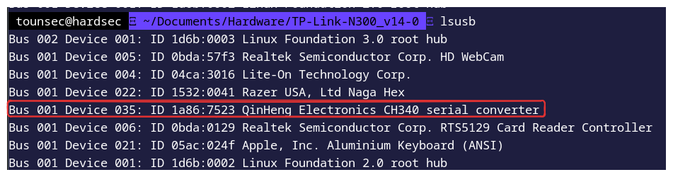
To interact with the UART serial console:
screen /dev/tty<USB> 115200
or
putty
or
minicom
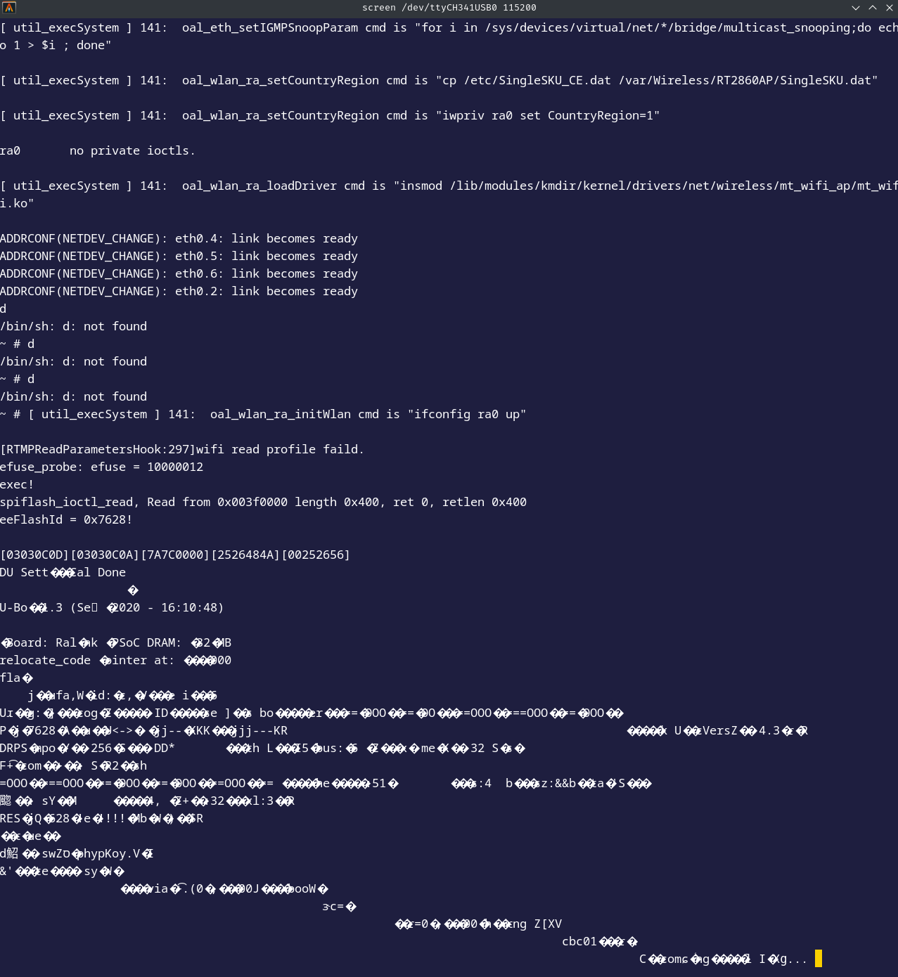
We quickly realize that it’s not possible to enter commands: we’re in fact in a read-only shell. CTRL+A then :quit to exit the console with screen.
How do you counter this handwriting protection?
At first, out of logic, I thought there must be something blocking traffic between the TX pin on my CH340G and the RX pin on the router. A little digging soon revealed a rather suspicious SMD-type resistor right in front of the RX pin on the router (R18). This is a fairly common method used as security for the UART to block writing to the serial console, it cuts off the transmission emitted from the TX pin of the USB, the RX pin of the PCB does receive the data but when it transmits it to the CPU for interpretation, the resistor blocks it.
With a multimeter, we get a value of 1kΩ on this resistor, so it could be our culprit.
Before you get too excited, let’s do a logical analysis based on the following connection:
- GND => GND
- TX => RX
- CHAN 1 => TX
After running this test to confirm that the problem occurred when receiving data from the RX pin of the router and not from the TX pin of my CH340G, there is no loss of data at the transmission level, so the bits are transmitted correctly, the problem does indeed come from the router and therefore most probably from the 1kΩ SMD resistor.
Well, to check one last time before removing the resistor, I decided to supply 5V for a short while from my CH340G just to test and see if I could enter any commands.
It works! So we have indeed found our culprit. I thought that unsoldering the resistor (R18) would be too dangerous for the integrity of the others, given their very small spacing (2 other SMD resistors very close together), but with a angled precision pliers, it did the trick. We could also have made a bridge with tin wire between the router’s RX pin and the output of the resistor on the circuit that blocks the transmission of bits sent by the CH340G’s TX pin.
 We can see that we have a default root shell without prior authentication!
Find firmware information
You can retrieve some information about the firmware.

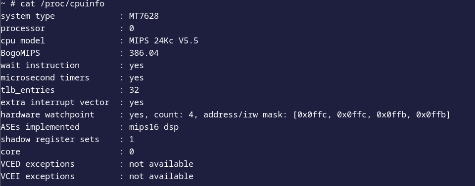
In fact, the version of the linux kernel is very old.
Extracting system files
To begin with, let’s take a look at which system files can be read and, above all, written to
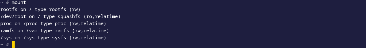
We can see that we have read and write permissions for:.
- rootfs
- proc
- ramfs
- sys
In general, rootfs, proc and sys are write-restricted for security reasons, so we’re left with ramfs (/var). Note that, as the name suggests, storage is intended for RAM, which is volatile, so when the router is rebooted, our actions will be erased.
Let’s take a look at the busybox functions available on our router
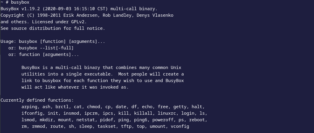 We notice that busybox is limited in terms of functionality, but we have tftp!
Before continuing, make sure you have access to the router’s network either via an ethernet bridge between your router and your computer or wirelessly. Install tftp and configure its server on your computer, then follow this guide HERE (remember to configure in relation to the router’s network). The following repository may be useful, as it gathers useful binary files to compile for the MIPS architecture HERE. Here we’ll need busybox-mipsel as the processor takes MIPSel into account, so in little-endian HERE.
Now go to /var/tmp and download busybox-mipsel using tftp.

Give permissions to the binary and run it, we have all the functionality that was normally restricted by the router’s original busybox.
chmod +x busybox-mipsel
./busybox-mipsel
All that’s left to do is make a system file archive and transfer it to our tftp server!
./busybox-mipsel tar cvf ./fs.tar ../../
tftp -pr fs.tar -l fs.tar 192.168.0.100
Conclusion
We achieved our initial goal of retrieving system files from the router via the serial console using the UART serial communication protocol. In the future, we plan to extract the firmware from the flash memory, which communicates with the CPU via the SPI serial communication protocol, and to reverse engineering this firmware.
I’d also like to point out that, despite the possibility of performing many more operations via the UART, especially with unauthenticated root access, this was not our original aim.